Wireless Laboratory Experiment Design Using Software Radios
Senior Project (SJSU)
Designed remotely accessible wireless laboratory experiments for SJSU's Electrical Engineering Department. The development of this project was motivated by the pandemic of 2020, which disturbed academic learning for students countrywide. This shift in the learning environment limited students' access to critical tools, such as laboratory equipment, which was essential for their academic success. Without the proper tools and equipment, students would be unable to develop the necessary skills required to compete in the job market. This issue instilled the primary motive for creating an easily accessible remote learning environment through wireless radios.
Parts Invlolved
External Laptop, VPN (Cisco AnyConnect), School Computers, MATLAB, Simulink, ADALM-PLUTO Radios, and Radio Transmitters/Receivers
The illustration below depicts the experiment flow and the layout of SJSU EE 160 Radio Lab (room ENGR 238)
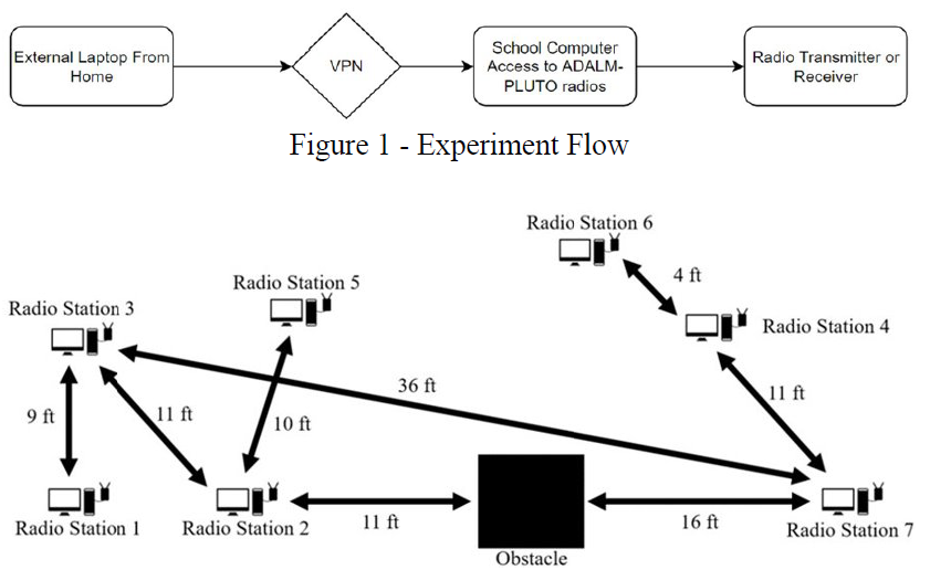
Experiment Flow and ENGR 238 Lab room layout
Initial Probelms and Methodology
Overall, a total of four experiments were designed. The bottom two experiments represent only 2 experiments involving Dual Sideband Suppressed Carrier. Other experiments involved On-Off keying (OOK), Amplitude-shift keying (ASK), and frequency-shift keying (FSK) modulation techniques.
Dual Sideband with a Suppressed carrier (DSB-SC)
The bottom two examples show DSB-SC transmitters and receiver models for two DSB-SC experiments. These two experiments represent a DSB-SC and DSB-SC with QM (Quadrature Demodulation). The designs needed modifications as the reception was poor. The solutions are shown below in the Final Models Section.
DSB-SC refers to a modulation scheme where the carrier is not included in the transmitted AM signal. The design for the transmitter and receiver is shown below. This design transmits a sinusoidal wave. DSB-SC refers to a modulation scheme where the carrier is not included in the transmitted AM signal. Note how the signal output from the radio is not passed through any block other than the DC blocker.
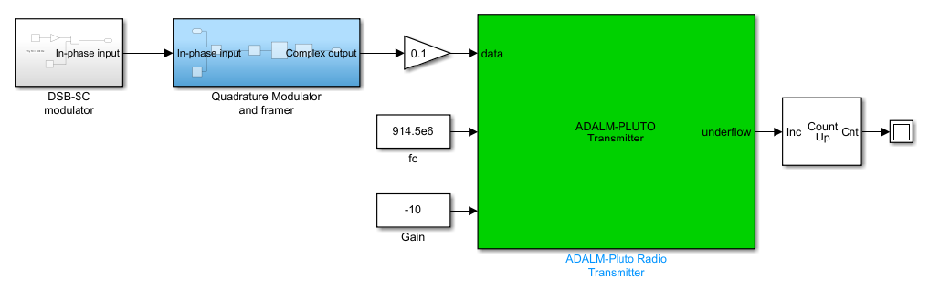
DSB-SC Transmitter Model
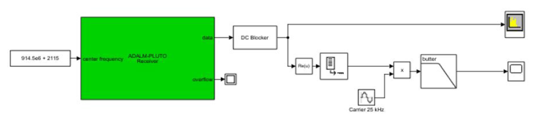
DSB-SC Receiver Model
DSB-SC Transmitter Model
DSB-SC Receiver Model
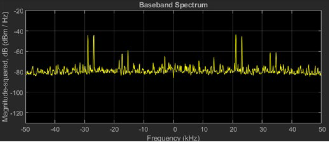
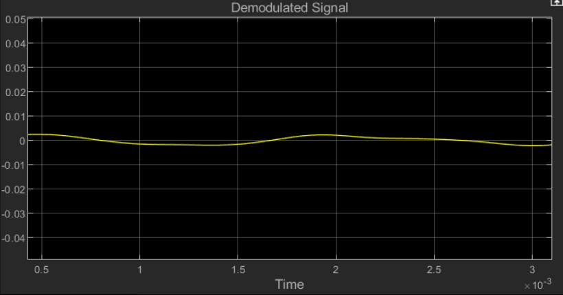
The baseband spectrum and demodulated signal are shown above. Note how poor the signal is and does not reflect the original transmitted sine wave. This is also independent of the fact that, in the baseband spectrum, the peaks of the sinusoidal waves can be easily seen
Quadrature Modulation consists of two legs: the In-Phase demodulator and the Quadrature
demodulator. Both are 90 degrees out of phase. This implementation uses DSB-SC to implement a quadrature-modulated signal. The transmitter and receiver model is shown below.
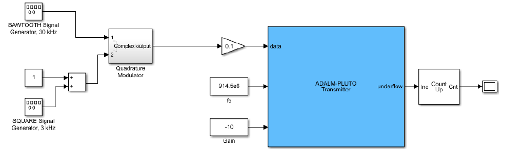
DSB-SC with Quadrature Demodulation Transmitter Model
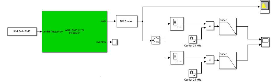
DSB-SC with Quadrature Demodulation Receiver Model
DSB-SC with Quadrature Demodulation Transmitter Model
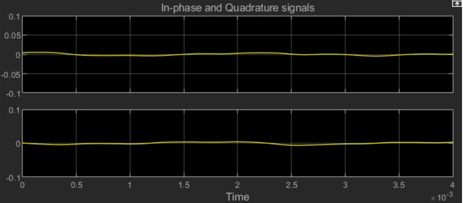
DSB-SC with Quadrature Demodulation Receiver Model
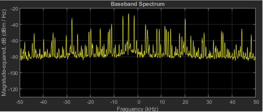
The baseband spectrum and the demodulated signals are shown above. Note how there is no discernable signal both in the in-phase and quadrature signals.
Resulting Final Models and Solutions
MATLAB’s simple phase-locked loop design where the multiplier block is treated as a phase detector. This PLL was mainly used in a lot of the Amplitude Modulation techniques to fix the frequency error. For example, DSB-SC and DSB-LC use the phase-locked loop model.
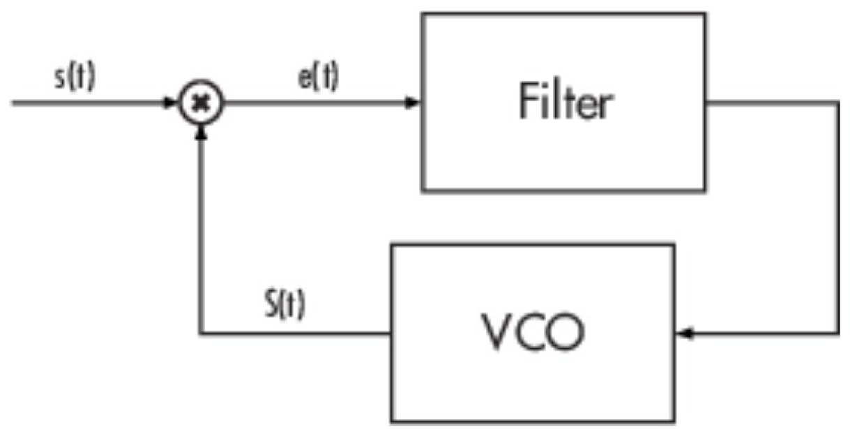
MATLAB PLL (Phased Locked Loop) Model Design
To fix frequency errors in the suppressed carrier signal, a PLL was made between the Butterworth filter and the product block by adding a VCO. An automatic gain controller was also added to stabilize the input signal.
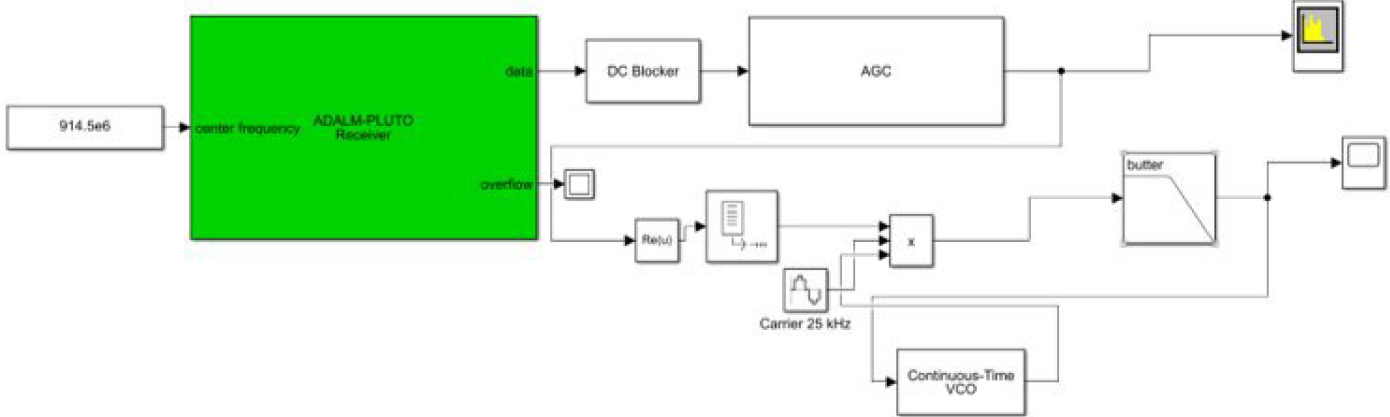
Receiver model for the DSB_SC with a PLL and AGC
The images below show the received spectrum and the demodulated signal. Note that, while the noise floor is higher in the spectrum, the demodulated signal actually shows a sinusoidal wave.
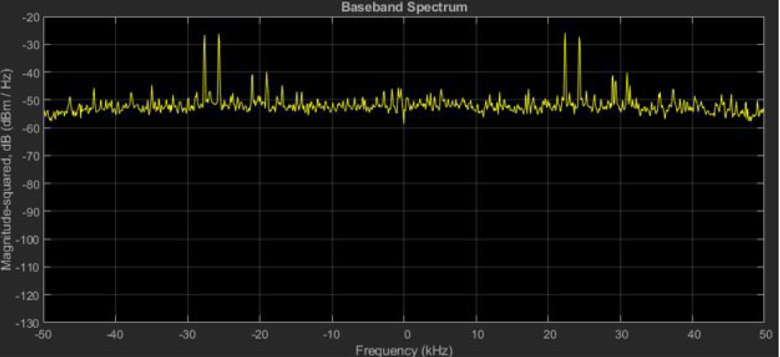
DSB-SC baseband Spectrum from the modified receiver model
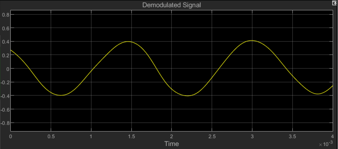
DSB-SC Demodulated Signal from the modified receiver model
The bottom image shows the modified DSB-SC Quadrature Demodulation Receiver, which contains an AGC and a PLL. The purpose of the AGC is to increase the gain and to maintain the gain at a constant level to account for the radio’s relative distances. There are two phase locked loops or PLLs in this model because of the split between the real and imaginary parts for the In-phase and Quadrature Signals. The In-phase and Quadrature Signals with the modified receiver model show that when the In-phase part of the signal is high, the Quadrature part is low, unlike the initial model where the signal was flat.
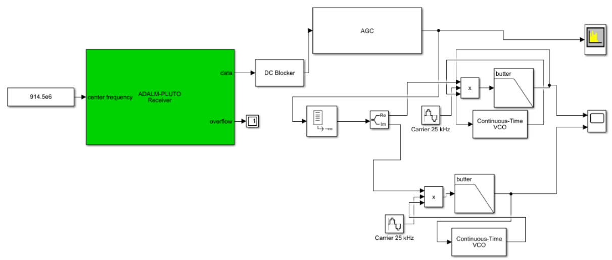
DSB-SC with Quadrature Demodulation containing an AGC and PLL in the receiver model
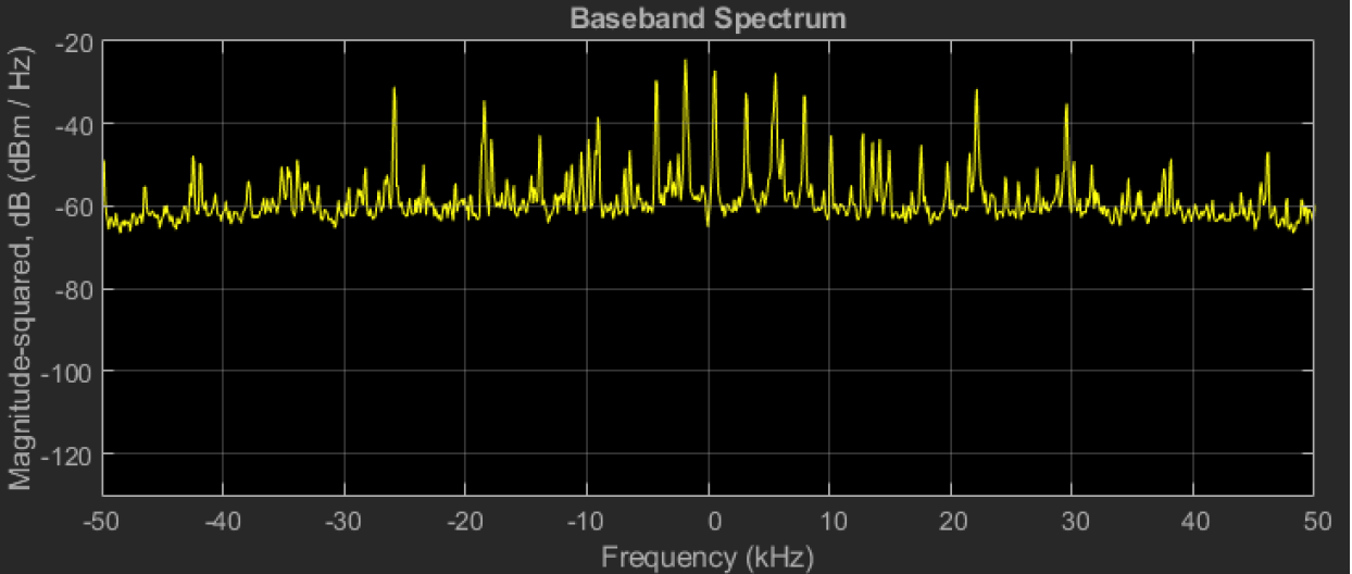
DSB-SC Quadrature Demodulation baseband Spectrum from the modified receiver
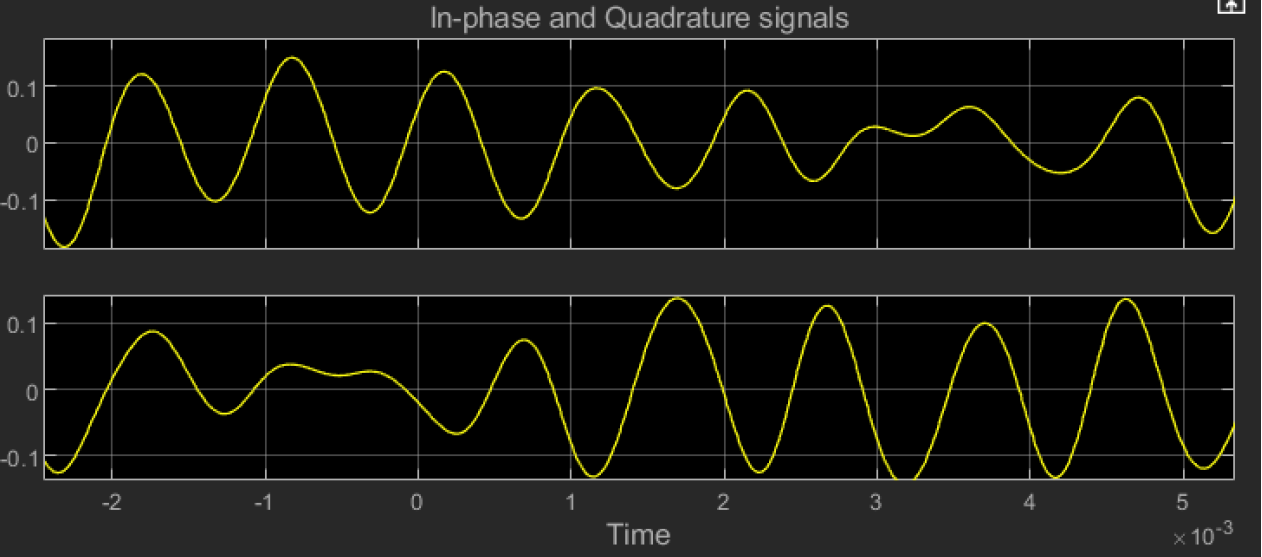
DSB-SC with Quadrature Demodulation In-phase and Quadrature Signals from the modified receiver