EMG Measurement System
Electronics for Biomedical Applications
Designed and 6 stage EMG measurment system. The circuit can detect muscle activation by pickng up on electric potential on the skin. The EMG uses electodes to translate electrical signals transmitted from motors neurons that couse muscle contract.
EMG System Demonstration
Parts and St
Materials:
- 3x LF353 IC Chip
- 1x INA126 IC Chip
- 1x EMG Cables (set of 3)
- 3x EMG Electrodes
- 2x 9V Battery
- 2x 9V battery clips
- 1x 0.01 uF Ceramic Disc
- 1x 1.0 uF Ceramic Disc
- 1x 150kOm 1%
- 3x 150 kOhm 1%
- 2x 1 MOhm 1%
- 2x 80.6 kOhm 1%
- 6x 10 kOhm 1%
- 1x 1 kOhm 1%
- 2x 1N4008 Diode
- Jumper wires
- 3x Alligator clip cables
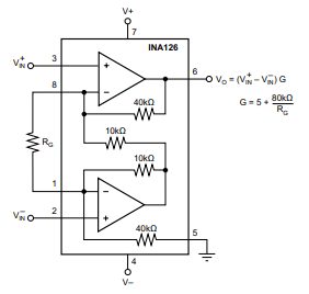
Stage 1: INA126 Differential Input Amplifier Diagram
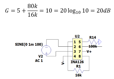
Stage 1: INA126 LTspice Diagram for a gain of 10 or 20dB
The EMG design, originally from instructables.com, was modified to use an INA126 in place of the unavailable INA106, with adjusted gain to match the original specifications. The datasheet OPAMP and LTspice schematics are shown above.


Stage 2: LF353 Inverting Op Amp with a gain of 23.52 dB
The model illustrates the circuit's second stage, featuring 10k and 150k Ohm resistors linked to the LF353 Op Amp, yielding a calculated gain of 23.53 dB.
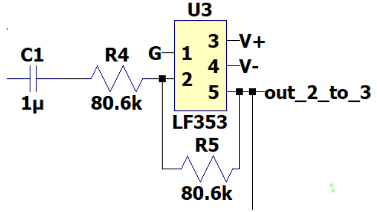
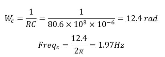
Stage 3: LF353 Op Amp High Pass filter with a cutoff frequency of 1.97Hz
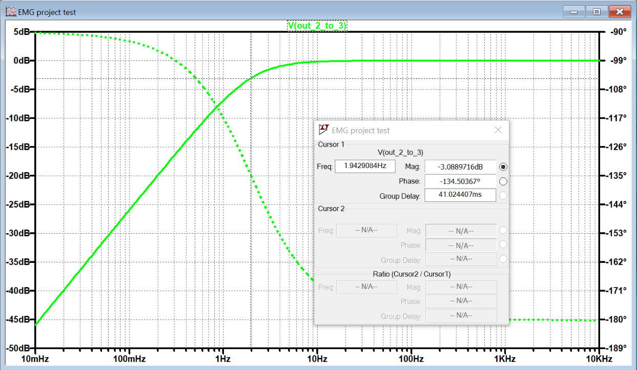
Stage:3 LTspice Bode Plot for stage 3
The depicted model and bode plot shown above represent the circuit's third stage, featuring two 80.6k Ohm resistors and a 1 uF capacitor linked to the LF353 op amp, resulting in a cutoff frequency of 1.97Hz.
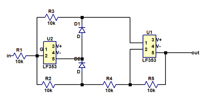
Stage 4: Full-Wave Rectifier and Two (2 LF353 Op Amps and 2 1N4008 Diodes)
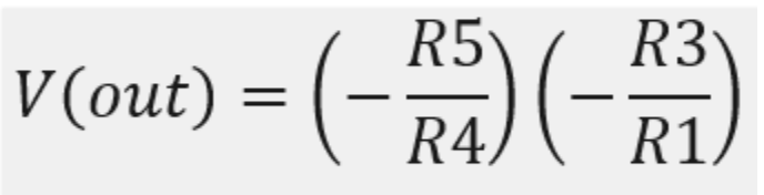
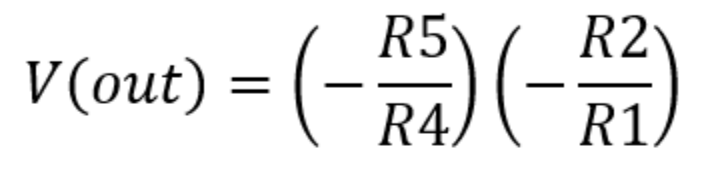
Stage 4: Output Voltage when V is negative (Top) and output when V is positive (Bottom)
The model above illustrates the circuit's 4th stage: a full-wave rectifier built with five 10k Ohm resistors, two 1N4008 diodes, and LF353 op amps. This stage rectifies the signal, making all of it positive for microcontroller compatibility, and includes a low pass filter to convert AC signal into DC voltage.
The above model and bode plot represent the circuit's 5th stage, a low pass filter with a cutoff frequency. This stage comprises a 0.01 uF ceramic disc capacitor and two 150k Ohm resistors connected to the LF353.
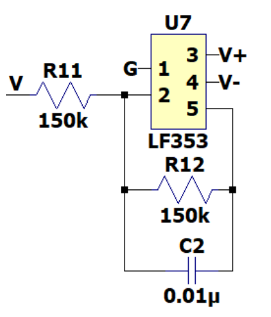
Stage 5: Low pass filter with cutoff frequency 1.97Hz
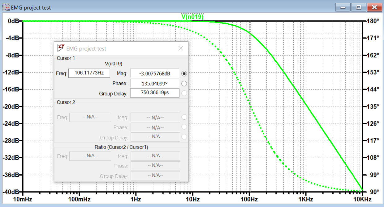
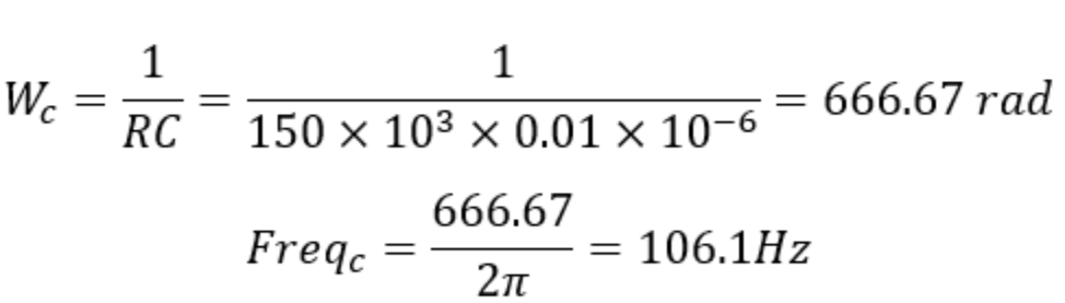
Stage 5: Low pass filter bode plot and cutoff frequency equation
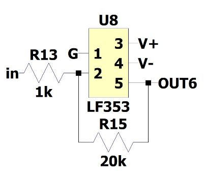
Stage 6: Inverting Op Amp with LF353 with a gain controller (1k and potentiometer resistor)
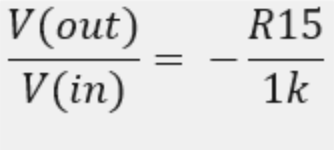
Stage 6: Gain
The model above depicts the sixth stage of the circuit, which is composed of 1k and potentiometer resistors conncected to LF353 Op Amp. Since EMG input signal is from 10uV to 90mV, the gain can be adjusted to proeprly capture the EMG signal from the diffrent muscles. The Overall bode plot of the stage circuit is shown bellow. The total gain of all the stages is 69.54 dB or a total Vout/Vin of 3000.
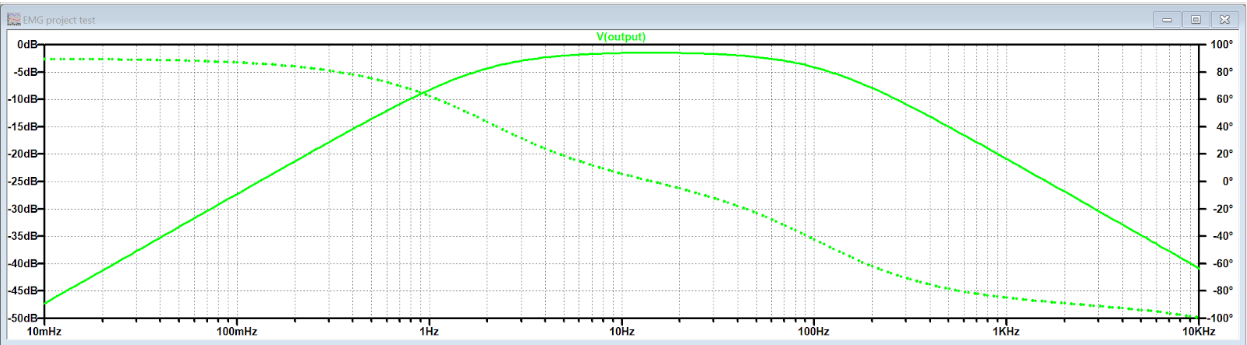
Stage 6: Inverting Op Amp with LF353 with a gain controller (1k and potentiometer resistor)
Key insights into myoelectric activity and muscle monitoring systems were gained through this project. The principles behind nerve activated muscle potentials were explored and the capability to detect these electric potentials through surface methods was developed. Noise issues were encountered and it was discovered how op-amp based circuits can enhance signal clarity. The project involved setting up muscle sensors and reading data using an Arduino, breadboard, and op-amps.
Challenges identified included electrode placement and interference with the signal waveform. It was found that the closer the electrodes were to the muscle, the cleaner the signal obtained. The importance of these monitoring systems in various applications was recognized, emphasizing the need to understand the components used in such designs.
Technical challenges included simulating the circuit on LTspice and handling component installation. Issues were experienced with the INA126 differential op-amp, which were overcome through online collaboration and seeking help from a professor. The project successfully simulated an EMG and read from the final physical circuit.
Finally, it was discovered how muscle sensor systems can eliminate noise using a bandpass filter. The Arduino muscle monitor allowed the observation of motor signals and the understanding of the relevance of muscle monitoring systems or EMG devices in the medical field. As a result, the understanding of muscle sensors and the characteristics of their waveforms was enhanced.
References
Technologies, A., & Instructables. (2017, November 01). DIY Muscle Sensor / EMG Circuit for a Microcontroller. Retrieved November 20, 2020, from https://www.instructables.com/Muscle-EMG-Sensor-for-a-Microcontroller/
Tighe, M. (2015, March 25). EMG Success! Retrieved November 20, 2020, from https://prostheticoss.wordpress.com/2015/03/19/emg-success/
The model above depicts the sixth stage of the circuit, which is composed of 1k and potentiometer resistors conncected to LF353 Op Amp. Since EMG input signal is from 10uV to 90mV, the gain can be adjusted to proeprly capture the EMG signal from the diffrent muscles. The Overall bode plot of the stage circuit is shown bellow. The total gain of all the stages is 69.54 dB or a total Vout/Vin of 3000.
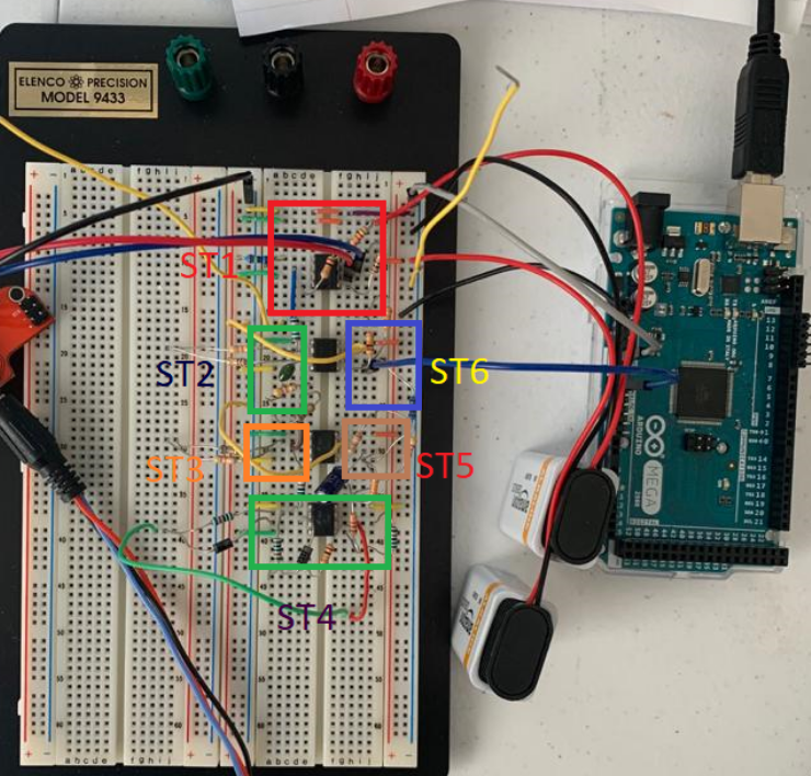
Complete Circuit